7.1 Calculation formula of rectangular section cylindrical spiral compression spring
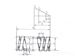
Load deformation diagram of rectangular cross-section compression spring
Table 12-2-36 Calculation formula of rectangular section cylindrical helical compression spring
| Project | Unit | Formulas and data | |
| Maximum working load Pn | N | Pn=(ab√ ab/βD)Tp=b√ ab/βCTp In the formula, C=D/a, Retrieved from Tables 12-2-37 β Is the coefficient, obtained from Figures 12-2-12 A=D/C=D2/C+1,D2 Determine based on spaceb=(b/b)a,b/a retrieved from Tables 12-2-37,Tp retrieved from Tables 12-2-6 |
|
| Deformation under maximum working load Fn | mm | Fn=γPn*D3n/Ga2*b2 =γPn*C2n*D/Gb2 In the formula,γ is the coefficient, which is taken as the effective number of turns according to Fig. 12-2-11 |
|
| stress τ | MPa | τ=βPn*D/ab√ ab=βPn*C/b√ ab,if τ>Tp,it need to be recalculated.
In the formula,β Is the coefficient, obtained from Figures 12-2-12 |
|
| Effective coils n | coils | n=Ga2*b2Fn/γPD3=GFna(b/a)2/γPn*C3 | |
| Spring stiffness P ‘ | N/mm | P‘=Ga2*b2/γD3n | |
| Working ultimate load Pj | N | Pj=ab√ ab/βDTj
Class I load: Tj≤1.67Tp Class Ⅲ load:Tj≤1.12Tp |
|
| Deformation F under working ultimate load Fj | mm | Fj=Pj/P ‘ | |
| Minimum working load P1 | N | P1=(1/3-1/2)Pj | |
| Deformation F1 under minimum working load | mm | F1=P1/P ‘ | |
| Spring outer diameter D2
Spring pitch diameter D Spring inner diameter D1 |
mm | D2 set according to actual space requirements
D=D2-a D1=D2-2a |
|
| End structure | The end is tightened and ground flat, and the support ring is 1 turn | The end is tight and not ground flat, and the support ring is 1 turn | |
| Total coils n1 | coil | n1=n+2 | n1=n+2 |
| Free height H0 | mm | H0=nt+1.5b | H0=nt+3b |
| Pressing height Hb | mm | Hb=(n+1.5)b | Hb=(n+3)b |
| Pitch t | mm | Generally, it take t=(0.28-0.5)D2 | |
| Spacing δ | mm | δ=t-b | |
| Working Stroke h | mm | h=Fn– F1 | |
| Helix angle α | (°) | α=arctant/πD | |
| Extension Length L | mm | L=n1πD | |
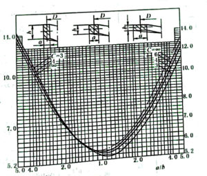
Figure 12-2-11 Coefficient γ value


