4.4 Application Example of Cylindrical Helical Tension Spring
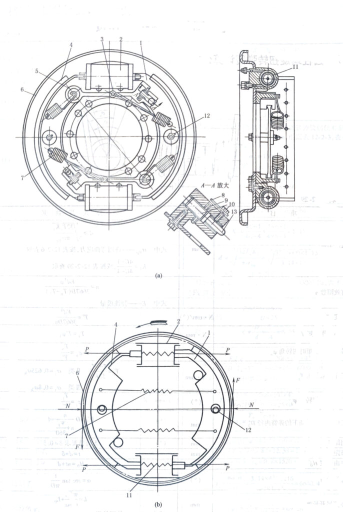
Figure 12-2-7 shows the balanced shoe brake of ZL50 wheel loader used in mines. Figure a is the structure diagram. Figure b is the force diagram. When braking, the piston of brake cylinder 2 is pushed out under the action of oil pressure. Press the two brake shoes 1 on the brake drum (not shown in the figure). When the brake is released, the oil pressure in brake cylinder 2 is released, and brake shoe 1 is pulled back and reset under the action of extension spring 7. Since the force on the brake shoes on both sides is balanced, the hub bearing is not subject to any additional load, and the wear of the friction lining is relatively uniform.

Figure 12-2-7 Balanced shoe brake
1-4 Brake shoe; 2 – Brake cylinder; 3 One spring seat; 5 – support plate: 6 – base plate: 7 – extension spring; 8 A reed; 9 One round; 10 One shot; 11 – Spring; 12,13-pin


