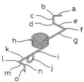
Manufacturing method of complex special-shaped spring
The invention relates to a forming method and equipment of a linear spring. The equipment includes more than three forming tools that can rotate a certain angle around the main shaft, advance to the center line of the main shaft and impact the wire at the same time, so as to form the linear spring. The method is characterized in that a rotary table equipped with a forming tool is rotated around the center line of the main shaft, so that the wire contact surface of at least one forming tool is in a direction suitable for wire forming; After the rotary table rotates, the forming tool is pushed to the extension direction of the center line with the help of a driving device to form the linear spring. The number of drives is more than the number of forming tools. The spindle can also rotate around its center line.

1. The invention relates to a forming method of a linear spring, which has the following steps: on the extension line of the center line of a main shaft, around the center line of the main shaft guided by the wire, three or more forming tools arranged radially are pushed forward in a direction perpendicular or basically perpendicular to the center line of the main shaft, The method is characterized in that the method also comprises the following steps: rotating a rotating table on which the forming tool is installed around the center line of the main shaft so that the wire contact surface of at least one required forming tool is in a direction suitable for the wire forming; And after the rotary table rotates, the required forming tool is pushed in the extension direction of the center line through one of many driving devices. The number of driving devices is more than the number of forming tools, and is arranged radially around the center line of the main shaft outside the rotary table for forming linear spring.
2. The method according to claim 1, which is characterized in that the main shaft rotates around the center line of the main shaft.
3. The method according to claim 1 or 2, which is characterized in that the wire is fed from the top part of the main shaft and in the step of rotating the rotating table equipped with the corresponding forming tool around the center line of the main shaft. As a result, the wire contact surface of one or more required forming tools is in the direction most suitable for wire forming.
4. A linear spring forming device in which three or more forming tools arranged radially around the center line of the main shaft guided by the wire are pushed towards the extension direction of the main shaft center line along the direction perpendicular to or basically perpendicular to the main shaft center line, and the forming tool strikes the wire sent in from the top part of the main shaft, The equipment is characterized in that it also includes: a first driving device for rotating the rotary table, and the corresponding track for moving the sliding components equipped with forming tools forward and backward is fixed on the rotary table. These sliding components can move forward and backward in the extension direction of the main shaft centerline perpendicular or basically perpendicular to the main shaft centerline;
A plurality of second driving devices, the number of which is equal to or more than the number of the sliding components, the second driving device is radially arranged outside the rotating table around the center line of the main shaft, for moving the required sliding components forward and backward towards the extension line of the center line of the main shaft; A third driving device for feeding the wire from the top part of the spindle; Wherein the first driving device and the second driving device are controlled to be synchronized with the third driving device.
5. The device according to claim 4, which is characterized in that the main shaft can rotate around the center line of the main shaft and can be converted between two cases. One is that the main shaft is fixed and cannot rotate through a connecting member, and the other is that the main shaft is connected with the rotating table through another connecting member so that it can rotate with the rotating table.
6. The device according to claim 4 or 5, which is characterized in that the second driving device is installed on a driving source mounting table which can rotate around the center line of the main shaft within a predetermined angle range when the driving source is located outside the rotating table.
7. The device according to claim 4 or 5 or 6, which is characterized in that the second driving device is provided with an arc cam capable of moving forward and backward in the extension direction of the main shaft centerline, and when a cam follower of the device on the sliding assembly moves closest to the main shaft in contact with the inner surface of the arc cam, The center of the arc inner surface of the arc cam is basically on the center line of the main shaft.
8. The device according to claim 7, which is characterized in that the arc cam can splice an auxiliary cam at its end.
Custom springs
Follows are some details for our springs.


