Application examples of cylindrical spiral torsion springs
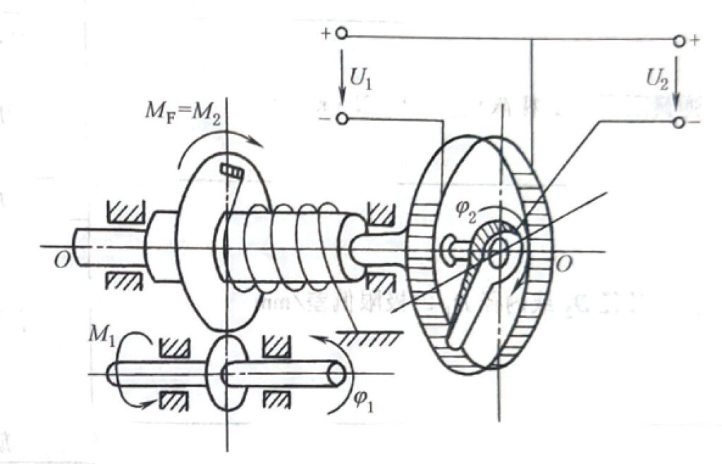
1) Figure 12-2-8 shows the application of torsion spring in electromechanical Force meter. When the torque M of the measured force F to the rotating shaft O-O is balanced with the spring torque MF of the torsion spring, the measured force F can be measured and expressed by the corresponding change value of voltage U.

Figure 12-2-8 Force meter
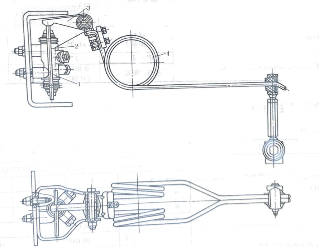
2) The braking force adjustment device in Figures 12-2-9 is composed of two torsion springs 4 in parallel, and the two ends of the load spring are respectively connected to the transmission frame and the rear axle of the car. Due to changes in the actual loading capacity of the car and changes in the rear suspension deflection caused by axle load transfer during braking, the torque of the torsion spring will change, thereby changing the control force of the comparison valve to play the role of automatic adjustment of the starting point.

Figure 12-2-9 Application of torsion spring on braking force adjustment device for freight cars
1. Inductive proportional valve; 2. Transmission framework; 3 levers; 4- Torsion spring


