Automatic spring coiling machine coiling spring (no spindle coiling spring)
The process of rolling springs with a mandrel is not only labor-intensive and low in productivity, but also reduces material utilization and quality uniformity. Therefore, in mass production, automatic spring coiling machines (Figure 3-9) are widely used for spring rolling. It can automatically roll, cut, count, etc., and can complete the spring forming process in one working cycle, so it has low labor intensity, high production efficiency, high material utilization, and can achieve multi-machine operation. Moreover, it has a wide adaptability to the size and shape of springs. In addition to rolling cylindrical spiral compression springs, it can also roll conical, convex, concave and other non-cylindrical spiral springs; coils and non-coils, left-handed or right-handed, equal pitch and unequal pitch spiral springs; helical torsion springs with tangential straight tails, etc. The spiral tension spring is rolled into a single blank and then processed into a hook and loop. Currently, some spring rolling machines can directly produce hook and loop on the machine.
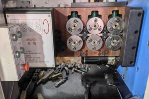
Figure 3-9 CNC Spring Coiling Machine
There are two basic methods and mechanisms for forming coils in automatic spring coiling machines: one is a single-rod spring coiling machine (Figure 3-10a); the other is a double-rod spring coiling machine (Figure 3-10b). Currently, these two models are still widely used in spring manufacturing.
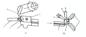
Figure 3-10 Schematic diagram of single-rod and double-rod coil spring machine
a) Single-rod spring coiling machine b) Double-rod spring coiling machine, information 1-guide plate 2-spindle 3-rod 4-cutting knife 5-spacing block
1 Operating principle of automatic spring coiling machine
As shown in Figure 3-11, the process of winding a spring with a double-top rod spring machine is as follows: after the spring material is pulled out from the rack 8, it passes through the straightening mechanism 7 (Figure 3-12) and the feeding mechanism 6 (Figure 3-13), and enters the forming mechanism through the guide plate 1. When it encounters the groove at the front end of the top rod 3, it forces the spring material to bend and deform. The spring coil is formed by winding the material around three friction points, which are the contact points between the spring material and the guide plate 1, two top rods 3, and the center spindle 2. For a single-top rod automatic spring machine (Figure 3-10), these three friction points are the contact points between the spring material and the guide plate 1, the work spindle 2, and the top rod (commonly known as the spring pin) 3. During the process of bending the spring material into a coil, the wire comes into contact with the inclined surface of the pitch block 5. Since the pitch block 5 is moved along the axis direction of the spring winding by the automatic spring machine’s pitch adjustment mechanism, it can produce the pitch of a spiral compression spring. When winding a spiral compression spring tube (support ring) or a spiral tension spring tube, the pitch block retreats to the back, and during winding, the last coil of spring coils is formed against the previously wound coil. When a spring is wound, the feeding mechanism stops feeding, and the cutter control mechanism forces the cutter 4 to cut off the spring. This repetitive operation achieves automatic spring forming.
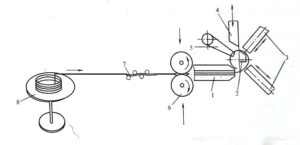
Figure 3-11 Working principle of the double-top rod coil spring machine
1. Guide plate 2. Spindle 3. Top rod 4. Cutting tool 5. Pitch block 6. Feeding mechanism 7. Straightening mechanism 8. Material rack Figure
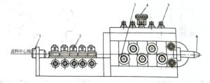
3-12 Straightening mechanism
1. Steel wire guide sleeve 2. Calibration roller 3. Adjustment handwheel 4. Pressure bolt 5. Discharge hole
The top rod can move forward and backward under the control of the spring diameter changing mechanism (Figure 3-14) to adjust the diameter of the spring or roll the variable diameter spiral spring.
When rolling cylindrical spiral springs, since the diameter remains unchanged, there’s no need for a diameter-changing cam. Simply adjust the relevant handles by hand during the rolling process to secure the top rod in place.
When rolling a variable diameter spiral spring, a corresponding variable diameter cam is required. As the spring material is continuously rolled into coils, the variable diameter cam also rotates accordingly to control the appropriate movement of the top rod, resulting in the rolling of the required variable diameter spiral spring.
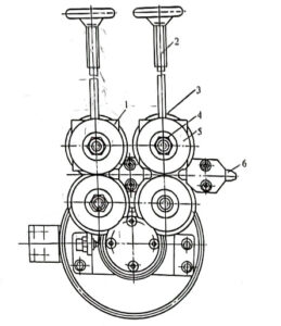
Figure 3-13 Feeding mechanism
1-Sliding bearing seat 2-Pressing bolt 3-Spring leaf 4-Roller shaft 5-Roller 6-Guide plate
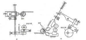
Figure 3-14 Automatic spring coiling machine variable diameter mechanism
a) Diameter changing mechanism for single-rod spring coiling machines b) Diameter changing mechanism for double-rod spring coiling machines
The variable pitch mechanism of the coil spring machine is driven by a variable pitch cam. When it is necessary to coil a variable pitch (commonly known as unequal pitch) spiral compression spring or other spiral spring, a variable pitch cam is required. Figure 3-15 shows the variable pitch mechanism of an automatic coil spring machine. Under the action of the variable pitch cam 2, a set of swing rod mechanisms push the pitch block 3 forward and backward to achieve the coiling of a variable pitch spring.
From the working principle of the coil spring machine mentioned above, it can be seen that the advantage of the single-rod automatic coil spring machine is that only one rod needs to be adjusted, so the adjustment time of the machine tool is less when changing the variety of springs. (And it can roll higher initial stress spiral tension springs, which is more convenient when changing left-handed and right-handed springs.) The advantage of the double-rod automatic coil spring machine is that the spindle no longer becomes a friction point for forming coils, but only plays the role of a cutting spindle. Therefore, when producing springs of different diameters, it is not necessary to frequently change the spindle. In addition, the central angle corresponding to the three friction points of the double-rod coil spring machine is larger than that of the single-rod coil spring machine, so it is more convenient and stable to coil larger springs. However, the double-rod automatic coil spring machine is cumbersome when changing left-handed and right-handed springs, and it is necessary to modify the entire rod adjustment assembly.
There are many factors that affect the quality of coil springs, such as the tensile strength, elongation, elasticity, strength ratio, dimensional accuracy and surface condition of the spring material, the accuracy of the machine tool equipment, the friction condition of the auxiliary tool and the wire contact part, the accuracy of the feeding length, and the winding speed and the technical level of the operator. Because these factors are related to the operation of the automatic winding machine, it is necessary to make fine adjustments to the machine tool during the use of the automatic winding machine. For specific adjustment methods, refer to the machine tool instructions.
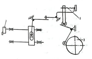
Figure 3-15: The distance adjustment mechanism of the automatic spring coiling machine
1. One lever with two bamboo rods 2. One driven protruding wire 3. One pitch block
2 Disadvantages of automatic spring coiling machine
The old-fashioned mechanical automatic spring coiling machine, known as the elephant, is already very familiar to the industry. The mechanical automatic spring coiling machine has made an indelible contribution to the spring industry with its simple structure, low price, and convenient maintenance. It still has a large share of the domestic spring manufacturing industry. However, with the emergence and promotion of automatic CNC spring coiling machines, the shortcomings of mechanical automatic spring coiling machines have gradually been exposed. Their shortcomings are mainly reflected in the following aspects.
In terms of power source, the wire feeding power of mechanical automatic spring coiling machines uses ordinary three-phase/single-phase motors. Compared to servo motors, ordinary motors have the characteristic that the angle is not easy to control. For example, if a 20-degree mark line is made on any ordinary motor shaft and then powered on to rotate, when the power is cut off, it is impossible to determine how many degrees the motor shaft has passed. Such a power source determines that automatic spring coiling machines cannot achieve high-precision wire feeding.
In terms of transmission system, the feeding line generally adopts the fan-shaped gear and electromagnetic clutch/one-way clutch. Most mechanical automatic winding machines use electromagnetic high-speed clutch one-way clutch. Due to structural reasons, it is necessary to install a brake device to ensure that the feeding line stops immediately when the clutch is disengaged. However, in practice, the brake device cannot achieve this accurately, resulting in a decrease in accuracy. At the same time, the clutch is a vulnerable part that often causes the machine to malfunction.
In theory, the reciprocating motion of the sector gear can achieve high precision. However, due to the inability to simultaneously meet the requirements of multiple tooth meshing and single tooth strength within a certain installation backlash, the actual precision is low. This is because of the presence of gear backlash and the accumulation of errors caused by multiple transmission links, which also reduces the accuracy of wire feeding.
Due to the fact that most mechanical automatic spring coiling machines rely on the same motor for both the feeding and forming (outside diameter, pitch, and cutting) processes, the forming cam also operates continuously during the feeding process to create the cutting action, thus limiting the length of the feeding line and preventing the production of long-sized spring collars with special specifications. However, there are also designs that use different motors for the feeding and forming systems, such as the CS-7 mechanical automatic oil seal spring collar machine produced in Taiwan, China, which can achieve unlimited feeding and thus enable the production of long-sized spring collars with special specifications.
In terms of forming, the mutual constraints of factors such as outer diameter, pitch, and cutting make debugging more cumbersome and require more time to produce the cam. It is also impossible to achieve complex debugging of the elastic balance. In addition, due to the simple structure and poor signal processing capabilities of mechanical automatic spring coiling machines, they cannot respond appropriately to problems that arise during production, such as material racks and wire materials.
The emergence of automatic CNC spring coiling machines has improved the above problems.


