Center shaft coiling springs
Center shaft coiling springs are commonly used springs for small to medium batch production and specialized designs with specific requirements. This method is also used for coiling torsion springs and some extension springs in large-scale production.
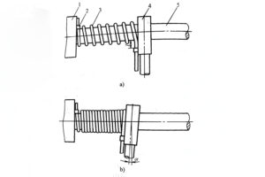
Figure 3-1 shows a schematic diagram of center shaft coiling. The center shaft is mounted on the main spindle chuck and rotates together with the main spindle. The main spindle moves the spring material feeding device left and right along the bed axis through gear exchange and screw, coiling the spring material around the center shaft to form a spring blank.
The support and coiling of helical compression springs are achieved through an automatic coiling device or by manipulating the opening and closing nut handle of the machine tool screw. The coiling methods include individual coiling and continuous multiple coiling. Individual coiling is generally used for manufacturing strip springs and oil seal springs, while continuous multiple coiling involves coiling a series of spiral springs at once, and then cutting them into individual springs according to dimensions.
In order to achieve the required dimensional accuracy after cold forming, it is necessary to accurately grasp the springback of different materials during spring design, process equipment design, and process specifications. There are many factors that affect springback, mainly including the mechanical properties of the material, the spring’s coiling ratio, and the process equipment. Springback is directly proportional to the tensile strength of the material and inversely proportional to the elastic modulus E. A larger value of a/E results in a larger springback. When the mechanical properties of the material are unstable, the springback is also unstable.

Figure 3-1: Center shaft coiling
a) Coiling of compression springs
b) Coiling of tension springs
1 – Machine tool chuck
2 – Chuck hook
3 – Spring blank
4 – Feeding device
5 – Center shaft
Springback is directly proportional to the coiling ratio C, i.e., a smaller coiling ratio results in less springback. This is because a greater degree of deformation corresponds to a larger proportion of plastic deformation within the material cross-section, resulting in less springback. To ensure good stress distribution and ease of manufacturing, the coiling ratio should be restricted within a certain range, usually between 4 and 16.
The distance between the guiding device and the center shaft also affects springback. A larger distance between the two leads to greater and uneven springback.
During the coiling process, a smaller coiling force and higher reverse rotation speed after coiling result in increased springback.


