4.2 Calculation Example of Cylindrical Helical Tension Spring
Table 12-2-26 Calculation Example of Cylindrical Helical Tension Spring 1
| Items | Unit | Formulas and Data | |
| Original condition | Maximum tension Pn Minimum tension P1 Working range h Spring external diameter Number of load actions N Spring material End structure |
N N mmmm |
350 176 12 ≤18 N<103times Carbon spring steel wire, grade C Circular hook ring compression center |
| Parameter calculation | Initial calculation of spring stiffness P’ | N/mm | P’=(Pn-P1)/h=(350-176)12=14.5 |
| Minimum working load of the spring P1 | N | As it is a Class III load, Pj≥Pn Considering that it is a tension spring, Pj in Table 12-2-19 should be multiplied by 0.8 times. For direct table lookup, change to P. Divide by 0.8,Namely:Pj=Pn*1/0.8=350*1/0.8=440 |
|
| Material diameter d and spring pitch diameter D | mm | Refer to Table 12-2-19 and select d=3,D=14,Pj=444.99,fj=1.527,P’d=291,Po=97.4 | |
| Effective coils n | coil | n=Pd‘/P’=291/14.5=20.06 take n=20 |
|
| Spring stiffness P’ | N/mm | P’=Pd‘/n=291/20=14.55 | |
| Deformation under minimum load F1 | mm | F1=(P1-Po)/P’=(176-97.4)/14.55=5.4 | |
| Deformation under maximum load Fn | mm | Fn=(Pn-Po)/P’=(350-97.4)/14.55=17.36 | |
| Deformation under ultimate load Fj | mm | Fj=fj*n*0.8=1.527*20*0.8=24.43 | |
| Spring outer diameter D2 | mm | D2=D+d=14+3=17 | |
| Spring inner diameter D1 | mm | D1=D-d=14-3=11 | |
| Free height H0 | mm | H0=(n+1.5)d+2D=(20+1.5)d+2*14=92.5 | |
| Length under minimum load H1 | mm | H1=H0+F1=92.5+5.4=97.9 | |
| Length under maximum load Hn | mm | Hn=H0+F2=92.5+17.36=109.86 | |
| Length under service limit load Hj | mm | Hj=H0+Fj=92.5+24.43=116.93 | |
| Expanded length L | mm | L=πDn+2πD=3.14*14*20+2*3.14*14=967.12 | |
| Checking calculation | Actual limit deformation | mm | Fn+Po/P’=17.36+97.4/14.55=20.05<Fj(24.43) |
| Actual limit load | N | Pj*0.8=444.99*0.8=356>Pn(350) | |
Table 12-2-27 Calculation Example II of Cylindrical Helical Tension Spring
| Items | Unit | Formulas and Data | |
| Original condition | Maximum tension Pn
Minimum tension P1 Working range h Number of load applications Spring material End structure |
N
N mm mm times |
340
180 11 ≤22 103~105 Oil quenched and tempered carbon spring steel wire Class B Round hook type |
| Parameter calculation | Initial spring stiffness P’ | N/mm | P’=(Pn-P1)/h=(340-180)11=14.5 |
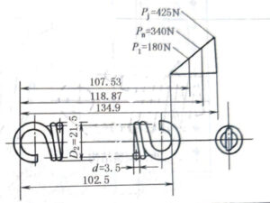
| Working limit load Pj | N | Because it is a class II load, Pj ≥ 1.25Pn, take Pj=1.25Pn=1.25 ×340=425, but considering the tension spring, the value of Pj in Table 12-2-19 should be multiplied by 0.8. In order to directly look up the table, divide 425 by 0.8, then Pj =405×1/0.8=531.25 |
|
| Spring material diameter d and spring diameter D | mm | According to Table 12-2-19, d=3.5, D=18, Pj =564.41,fj=2.221, P’d=254, Po= 109。 As the spring material is oil quenched and tempered carbon spring steel wire B,thus δb=1569
Now, Pj =564.41 and fj=2.221 obtained from Table 12-2-19 are corrected according to Table 12-2-18 Pj =1569/1570*564.41=564 fj=51*1569/0.79*105*2.221=2.250 |
|
| Effective turns n | coils | n=Pd‘/P’=254/14.5=17.5 take n=18 |
|
| Spring stiffness P ‘ | N/mm | P’=Pd‘/n=254/18=14.11 | |
| Deformation under minimum load F1 | mm | F1=(P1-Po)/P’=(180-109)/14.11=5.03 | |
| Deformation under maximum load Fn | mm | Fn=(Pn-Po)/P’=(340-109)/14.11=16.37 | |
| Deformation under ultimate load Fj | mm | Fj=fj*n*0.8=2.250*18*0.8=32.4 | |
| Spring outer diameter D2 | mm | D2=D+d=18+3.5=21.5 | |
| Spring inner diameter D1 | mm | D1=D-d=18-3.5=14.5 | |
| Free height H0 | mm | H0=(n+1.5)d+2D=(18+1)×3.5+2×18=102.5 | |
| Length under minimum load H1 | mm | H1=H0+F1=102.5+5.03 =107.53 | |
| Length under maximum load Hn | mm | Hn=H0+F2=102.5+16.37=118.87 | |
| Length under service limit load Hj | mm | Hj=H0+Fj=102.5+32.4=134.9 | |
| Helix angle α | (°) | α=arctan t/πD=3.5/3.14*18=3.54
t=d=3.5mm |
|
| Spring expansion length L | mm | L=πDn1+2πD*3/4=3.14*18*18+2*3.14*18*3/4=1102 | |
| Elastic property checking calculation | Actual limit deformation | mm | (Po/P’+Fn)*1.25=(109/14.11+16.37)*1.25=30.111<Fj(32.4) |
| Maximum working load Pn | N | Pn=Po+P’*Fn=109+14.11×16.37=339.9≈340 | |
| Actual limit load Pj | N | Pj*0.8=564×0.8=451.53>1.25×340
Namely, |
|
| Working drawing |  |
||


