Calculation of cylindrical helical compression spring
Table 12-2-21 Calculation example of cylindrical helical compression spring 1
| Items | Unit | Formulas and Data | ||||||||||
| Original condition | Minimum working load P1 Maximum working load Pn Working range h Spring outside Diameter D₂ Spring Type End Type Spring Material |
N N mm mm |
P1=60
Pn=240 h=36±1 D₂≤45 N=103~106 times The ends are tightened and ground, and the support rings at both ends are 1 circle each Carbon Spring Wire Grade C |
|||||||||
| Parameter calculation | Initial spring stiffness P’ | N/mm | P’=(Pn-P1)/h=(210-60)/36=5 | |||||||||
| Working limit load Pj | N | Because it is a Class Ⅱ load: Pj≥1.25P, so Pj=1.25×240=300 | ||||||||||
| Spring material diameter d and spring diameter D and related parameters | According to Pjand D conditions from Table 12-2-19:
|
|||||||||||
| Effective Coins n | Coin | n=Pd‘/P’=27/5=5.4
According to Table 12-10, take the standard value n=5.5 |
||||||||||
| Total Coins n1 | Coin | n1=n+2=5.5+2=7.5 | ||||||||||
| Spring rate P’ | N/mm | P’=Pd‘/n=27/5.5=4.9 | ||||||||||
| Deformation under working limit load Fj | mm | Fj=nfj=5.5*11.37≈63 | ||||||||||
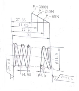
| Pitch t | mm | t=Fj/n+d=63/5.5+3.5=14.95 | ||||||||||
| Free height H0 | mm | H0=nt+1.5d=5.5*14.95+1.5*3.5=87.47,take standard value H0=90 | ||||||||||
| Spring Outside diameter D2 | mm | D2=D+d=38+3.5=41.5 | ||||||||||
| Spring inner diameter D₁ | mm | D₁=D-d=38-3.5=34.5 | ||||||||||
| Helix angle α | (°) | α=arctan t/πD=arctan 14.95/π*38=7.14 | ||||||||||
| Expanded length L | mm | L=πDn1/cosα=π*38*7.5/cos7.14=902 | ||||||||||
| Height at minimum load H1 | mm | H1=H0-P1/P’=90-60/4.9=77.76 | ||||||||||
| Height at maximum load Hn | mm | Hn=H0-Pn/P’=90-240/4.9=41.02 | ||||||||||
| Height at ultimate load Hj | mm | Hj=H0-Pj/P’=90-306.97/4.9=27.35 | ||||||||||
| Actual work range h | mm | h=H1-Hn=77.76-41.02=36.74≈36±1 | ||||||||||
| Work area scope | P1/Pj=60/306.97≈0.2;Pn/Pj=240/306.97≈0.8 | |||||||||||
| Height to diameter ratio b | b=H0/D=90/38=2.37<2.6 | |||||||||||
| Woring Drawing |  |
skills requirement 1. Rotation: right-hand 2. Effective coins n=5.5, total coins n1=7.5 3. Expanded length L=902mm 4. The accuracy requirements are not specified according to CB1239.2-2 level 5. The spring is treated with stress relief and tempering |
||||||||||
Table 12-2-21 Calculation example of cylindrical helical compression spring 2
| Name | Unit | Formulas and Data | |
| Original condition | Maximum working load Pn Minimum working load P1 Spring diameter D Working range h |
N N mm mm |
Pn=420 P1=200 D=32 h=10 |
| Spring Category – Valve Spring Camshaft speed nmax Material End type |
r/min | Class Ⅱ Spring,N=103~106 times Oil quenched and tempered carbon steel spring wire is used for the valve, both ends are tightened and ground flat, and the number of supporting rings is 1 |
|
| Parameter calculation | Allowable stress τp | MPa | According to table 12-2-4,σb=1422,so τp=0.4,σb=568.8 |
| Initial C and K | According to the formula,8/πKC3=τpD2/Pn=568.8*322/420=1386.7 | ||
| Material diameter d | mm | d=D/C=32/7.7=4.16, take d=4.5 | |
| Determine the winding ratio C | C=D/d=32/4.5=7.1 | ||
| Determine the curvature coefficient K | K=(4c-1)/(4C-4)+0.615/C or check table 12-2-20 K=1.21 |
||
| Spring stiffness P’ | N/mm | P’=(Pn-P1)/h=(420-200)10=22 | |
| Deformation under minimum working load F1 | mm | F1=P1/P’=200/22=9.1 | |
| Deformation under maximum working load Fn | mm | Fn=Pn/P’=420/22=19.1 | |
| Deformation f during compaction Fb | mm | According to the stipulation that the working area of the compression spring should be 20% – 80% of the total deformation, take Fn=0.65Fb,So Fb=Fn/0.65=29.4 | |
| Compression load Pb | N | According to the same provisions of the above item,Pb=Pn/0.65=420/0.65=646 | |
| Effective Coins n | Coil | n=Gd4Fn/8PnD3=7900*4.54*19.1/8*420*323=5.63,take n=6 | |
| Total Coins n1 | Coil | According to table 12-2-14,n1=n+2=6+2=8 | |
| Pressing height Hb | mm | According to table 12-2-14,Hb=(n+1.5)d=(6+1.5)*4.5=33.75 | |
| Free height H0 | mm | H0=Hb+ Fb=33.75+29.4=63.15, take H0=65 | |
| Pitch t | mm | According to table 12-2-8,t=(H0-1.5d)/n=(65-1.5*4.5)/6=9.71 | |
| Helix angle α | (°) | α=arctan t/πD=arctan 9.71/3.14*32=5.52° | |
| Expanded length L | mm | L=πDn1/cosα=π*32*8/cos5.52°=808 | |
| Pulsating fatigue limit τ0 | Mpa | According to table 12-2-16,when N=107,τ0=0.3σb=0.3*1422=420 | |
| Minimum shear stress τmin | Mpa | τmin=8KDP1/πd3=8*1.21*32*200/3.14*4.53=216 | |
| Maximum shear stress τmax | Mpa | τmax=8KDPn/πd3=8*1.21*32*420/3.14*4.53=454 | |
| Fatigue safety factor s | S=(τ0+0.75τmin)/τmax=(420+0.75*216)/454=1.28
S≈Sp=1.3-1.7 |
||
| Spring natural frequency f | 1/s | f=3.56*105*d/nD2=3.56*105*4.5/6*322=260.7 | |
| Forced vibration frequency fr | 1/s | fr=nmax/60=1400/60=23.3 | |
| Resonance checking calculation f>10 fr,namely 260.7>10×23.3 | |||


